
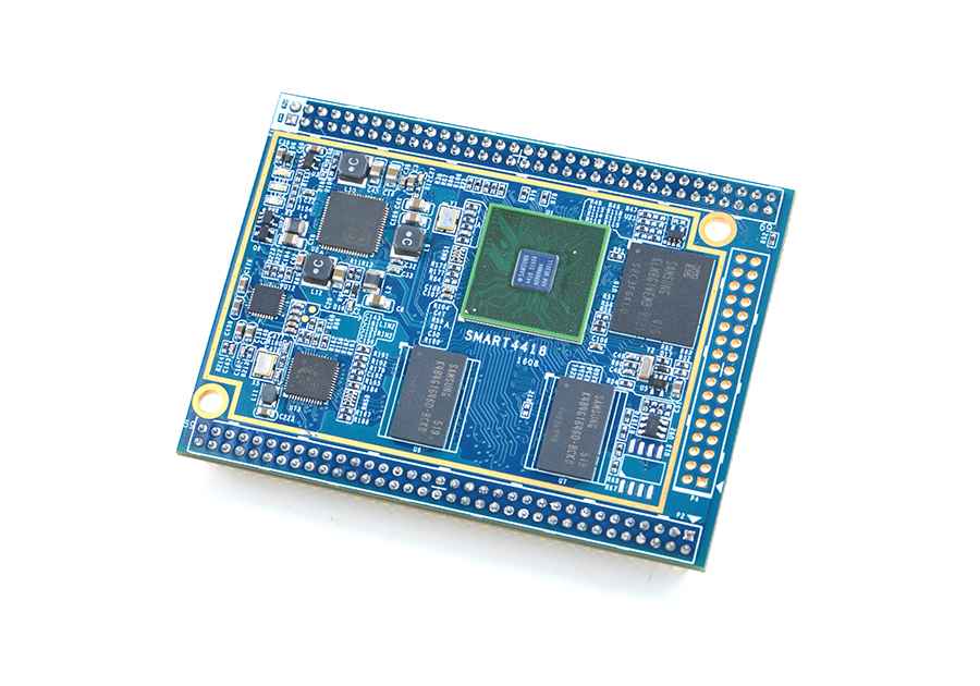
FriendlyELEC Smart4418 CPU board (8G eMMC,1G RAM)
3 647 Ft
Több mint 100.000 termék azonnal raktárról

Megbízható, elismert világmárkák
30 év szakmai tapasztalat

Versenyképes árak
Introduction
- The Smart4418 CPU board is a quad core Cortex A9 CPU board designed and developed by FriendlyElec for industrial applications. As a successor of the Smart210 CPU board it uses the Samsung Quad Core Cortex-A9 S5P4418 SoC with dynamic frequency scaling up to 1.4GHz. The standard Smart4418 CPU board has 1GB DDR3 RAM and 8GB eMMC. It has the AXP229 PMU enabling software power off/on and wake-up functions. In addition its Gbps Ethernet and audio jack make it suitable for various industrial applications.
- The Smart4418 CPU board has 2.0mm pitch double row pin headers(P1, P2 and P4) containing 174 pins in total. These pins contain most popular interface pins. By default we have P1 and P2 soldered on the board and leave P4 for users' applications. It works with various FriendlyElec LCDs e.g. 3.5"LCD, 4.3"LCD, 5"LCD, 7"LCD and 10.1"LCD.
- In addition we have a Smart4418/6818SDK carrier board which enables the Smart4418 CPU board's Gbps Ethernet.In addition FriendlyElec will soon release a Samsung Octa Core Cortex-A53 S5P6818@1.4GHz based board which is pin to pin compatible to the Smart4418 CPU board.
- For more details about the Smart4418 SDK carrier board V1606 refer to Smart4418SDK 1606.
Features
- CPU: Samsung S5P4418 Quad Core Cortex-A9, with dynamic frequency scaling from 400M Hz to 1.4G Hz
- PMU Power Management Unit: AXP228. it supports software power-off and wake-up functions.
- DDR3 RAM: 1GB 32bit DDR3 RAM
- Ethernet: Gbps Ethernet(RTL8211E) with unique MAC
- eMMC: 8GB
- Audio: 1 x audio codec chip, 1 x onboard Microphone and 1 x audio jack
- LED: 1 x Power LED, 2 x GPIO LED
- Others: onboard thermistor
- PCB Dimension: 74 x 55 mm, Six-Layer
- Power: DC 5V, up to 1.2A
- OS/Software: u-boot, Android5.1/4.4, Debian8, ubuntu-core
- 3 x 2.0mm pitch double row pin header, 174 pins in total:
- USB 2.0 - Host x1, OTG x1
- Video output/Display - RGB Parallel I/F (24-bit), LVDS and HDMI 1.4a
- Video input - DVP Camera interface, ITU-R BT 601/656 8-bit and MIPI-CSI
- Audio input - Microphone
- Audio output - Audio jack (with headset detection) and HDMI audio
- Ethernet - 10/100/1000Mbps Ethernet x 1
- ADC - CPU internal ADC, 7 channels, 12-bit, range: 0 ~ 1.8V
- External interface - SDIO/MMC x2, SPI x2, I2C x3, UART x5, PWM x3, GPIOs x24
- Others - Power key input, RESET input, RESET output, RTC battery input
Pin Specification
|
P1 |
P2 |
|||||||||
|
Pin# |
Name |
Pin# |
Name |
Pin# |
Name |
Pin# |
Name |
|||
|
1 |
VDD_5V |
2 |
DGND |
1 |
UART0_TX |
2 |
UART0_RX |
|||
|
3 |
RTC_BATT |
4 |
GPIOB8 |
3 |
UART1_TX |
4 |
UART1_RX |
|||
|
5 |
NRESETIN |
6 |
GPIOC17 |
5 |
UART2_TX |
6 |
UART2_RX |
|||
|
7 |
MMC0_CMD |
8 |
MMC1_CMD |
7 |
UART3_TX |
8 |
UART3_RX |
|||
|
9 |
MMC0_CLK |
10 |
MMC1_CLK |
9 |
UART1_nCTS |
10 |
UART1_nRTS |
|||
|
11 |
MMC0_D0 |
12 |
MMC1_D0 |
11 |
CAM0_D0 |
12 |
CAM0_D1 |
|||
|
13 |
MMC0_D1 |
14 |
MMC1_D1 |
13 |
CAM0_D2 |
14 |
CAM0_D3 |
|||
|
15 |
MMC0_D2 |
16 |
MMC1_D2 |
15 |
CAM0_D4 |
16 |
CAM0_D5 |
|||
|
17 |
MMC0_D3 |
18 |
MMC1_D3 |
17 |
CAM0_D6 |
18 |
CAM0_D7 |
|||
|
19 |
MMC0_CD |
20 |
GPIOB24 |
19 |
CAM0_PCLK |
20 |
CAM0_VSYNC |
|||
|
21 |
PWRKEY |
22 |
SPI1_CS/GPIOC10 |
21 |
CAM0_HYNC |
22 |
GPIOB14 |
|||
|
23 |
GPIOB28/UART4_RX |
24 |
SPI1_MISO/GPIOC11 |
23 |
GPIOB16 |
24 |
HDMI_TX1P |
|||
|
25 |
GPIOB29/UART4_TX |
26 |
SPI1_MOSI/GPIOC12 |
25 |
HDMI_TX0P |
26 |
HDMI_TX1N |
|||
|
27 |
GPIOB30 |
28 |
SPI1_CLK/GPIOC9 |
27 |
HDMI_TX0N |
28 |
HDMI_TXCP |
|||
|
29 |
GPIOC15 |
30 |
GPIOC16 |
29 |
HDMI_TX2P |
30 |
HDMI_TXCN |
|||
|
31 |
GPIOB31 |
32 |
GPIOB18 |
31 |
HDMI_TX2N |
32 |
HDMI_HPD |
|||
|
33 |
GPIOD1/PWM0 |
34 |
I2C0_SCL |
33 |
I2C1_SDA |
34 |
I2C1_SCL |
|||
|
35 |
GPIOC13/PWM1 |
36 |
I2C0_SDA |
35 |
USB_OTG_ID |
36 |
SPI0_CS |
|||
|
37 |
USB_HOST_D- |
38 |
I2C2_SCL |
37 |
USB_OTG_D- |
38 |
SPI0_MISO |
|||
|
39 |
USB_HOST_D+ |
40 |
I2C2_SDA |
39 |
USB_OTG_D+ |
40 |
SPI0_MOSI |
|||
|
41 |
LCD_B0 |
42 |
LCD_B1 |
41 |
VBUS_5V |
42 |
SPI0_CL |
|||
|
43 |
LCD_B2 |
44 |
LCD_B3 |
43 |
LVDS_CLKP |
44 |
GPIOB25 |
|||
|
45 |
LCD_B4 |
46 |
LCD_B5 |
45 |
LVDS_CLKM |
46 |
DGND |
|||
|
47 |
LCD_B6 |
48 |
LCD_B7 |
47 |
LVDS_Y0P |
48 |
LAN_MDI1_N |
|||
|
49 |
LCD_G0 |
50 |
LCD_G1 |
49 |
LVDS_Y0M |
50 |
LAN_MDI1_P |
|||
|
51 |
LCD_G2 |
52 |
LCD_G3 |
51 |
LVDS_Y1P |
52 |
LAN_MDI0_N |
|||
|
53 |
LCD_G4 |
54 |
LCD_G5 |
53 |
LVDS_Y1M |
54 |
LAN_MDI0_P |
|||
|
55 |
LCD_G6 |
56 |
LCD_G7 |
55 |
LVDS_Y2P |
56 |
LINK_LED |
|||
|
57 |
LCD_R0 |
58 |
LCD_R1 |
57 |
LVDS_Y2M |
58 |
SPEED_LED |
|||
|
59 |
LCD_R2 |
60 |
LCD_R3 |
59 |
LVDS_Y3P |
60 |
DGND |
|||
|
61 |
LCD_R4 |
62 |
LCD_R5 |
61 |
LVDS_Y3M |
62 |
HP_DETECT |
|||
|
63 |
LCD_R6 |
64 |
LCD_R7 |
63 |
HP-R |
64 |
HP-L |
|||
|
65 |
LCD_VSYNC |
66 |
LCD_HSYNC |
65 |
LAN_MDI2_P |
66 |
LAN_MDI3_P |
|||
|
67 |
LCD_CLK |
68 |
LCD_DE |
67 |
LAN_MDI2_N |
68 |
LAN_MDI3_N |
|||
|
69 |
DGND |
70 |
BOOT_CS |
69 |
Mic-P |
70 |
Mic-N |
|||
|
P4 |
||||||||||
|
Pin# |
Name |
Pin# |
Name |
|||||||
|
1 |
MIPICSI_DP0 |
2 |
GPIOD8/PPM |
|||||||
|
3 |
MIPICSI_DN0 |
4 |
GPIOC7 |
|||||||
|
5 |
MIPICSI_DP1 |
6 |
GPIOC8 |
|||||||
|
7 |
MIPICSI_DN1 |
8 |
GPIOC24 |
|||||||
|
9 |
MIPICSI_DP2 |
10 |
GPIOC28 |
|||||||
|
11 |
MIPICSI_DN2 |
12 |
GPIOC0 |
|||||||
|
13 |
MIPICSI_DP3 |
14 |
GPIOC1 |
|||||||
|
15 |
MIPICSI_DN3 |
16 |
GPIOC2 |
|||||||
|
17 |
MIPICSI_DPCLK |
18 |
GPIOC3 |
|||||||
|
19 |
MIPICSI_DNCLK |
20 |
DGND |
|||||||
|
21 |
GPIOB9 |
22 |
ADC1 |
|||||||
|
23 |
GPIOB26 |
24 |
ADC3 |
|||||||
|
25 |
GPIOC4 |
26 |
ADC4 |
|||||||
|
27 |
AliveGPIO3 |
28 |
ADC5 |
|||||||
|
29 |
PWREN_SYS |
30 |
ADC6 |
|||||||
|
31 |
GPIOC14/PWM2 |
32 |
ADC7 |
|||||||
|
33 |
NRESETOUT |
34 |
DGND |
|||||||
Note:
- VDD_5V: Supply voltage, range:4.7 ~ 5.6V. We recommend a 5V/1.2A(MAX) power. You can lower the clock to decrease the power consumption. When the clock is lowered by 200MHz the power consumption roughly decreases 0.5W .
- BOOT_CS: Boot chip selection. When it is not connected or pulled up the board boots from eMMC otherwise it boots from SD card
- NRESETIN: Reset input. Activated when it is low. A reset signal is input to CPU from this pin
- NRESETOUT: Reset output. Activated when it is low. CPU's reset signal outputs to this pin.
- RTC_BATT: RTC's input, direct connection to a 3V power source. If the CPU board is powered on the RTC seat is powered by 3.3V external power otherwise when the CPU board is not powered on it is powered by the RTC battery.
- ADC1~7: CPU internal ADC, 12-bit, 7 channels 1~7, range:0 ~ 1.8V
- 10/100M Ethernet mode: LAN_MDI1_N/P=RX-/+, LAN_MDI0_N/P=TX-/+, four pins connected to RJ45
- 10/100/1000M Ethernet mode: LAN_MDI0_N/P~LAN_MDI3N/P, all eight pins connected to RJ45
- For more details refer to our carrier board's design:Smart210/4418 SDK
- For more details about the Smart4418 SDK carrier board V1606 refer to Smart4418SDK 1606.
- Smart4418 Schematic in pdf
Wiki: http://wiki.friendlyarm.com/wiki/index.php/Smart4418
github:https://github.com/friendlyarm
Smart4418 1512 Schematic : Smart4418-1512-Schematic.pdf
Smart4418 1608 Schematic: Smart4418-1608-Schematic.pdf
Smart4418 1512 Dimension: dimension (Smart4418-1512-Dimension(dxf).zip)
Smart4418 1608 Dimension: dimension (Smart4418-1608-Dimension(dxf).zip)
Bejelentkezés